Lab

The experimental campaign

One problem at several scales

A bubble column is designed and operated as a whole, but what it does as a whole is settled at the scale of single bubbles: how fast one rises, how it deforms, whether it drifts sideways, whether two of them merge, how much gas crosses its surface. Inside a working column those mechanisms cannot be told apart, because millions of bubbles are doing all of them at once. The campaign therefore works at two scales — isolating one mechanism at a time in small laboratory columns, then measuring the aggregate behaviour in a large-diameter one — so that what is observed at the top of the column can be traced to the physics underneath it.

Small scale · Work package b and c

Small-scale bubble columns

Six transparent acrylic columns, they differ in the section, in the injector carried on the bottom plate — a needle, rows of needles, and perforated plate — and in the optical access up the height, which is what decides the experiment each one can do. The working fluids range from water to the aqueous ionic-liquid mixtures the project has selected.

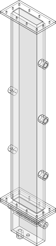
CAD elevation of the single-bubble column

Single-bubble column

A rectangular column releases single bubbles, tracked with a high-speed camera to study how they rise, change shape, and wobble in water and ionic liquid solutions, revealing the basic physics behind bubble behaviour in liquids.
CAD elevation of the rectangular bubble-swarm column

Bubble-swarm column

A rectangular column with perforated plates of different hole sizes generates a controlled bubble swarm, tracked through image analysis and gas holdup measurements to reveal flow-regime behaviour feeding into a broader theory of bubble columns.

CAD elevation of the cylindrical bubble-swarm column

Circular bubble-swarm column

The circular counterpart of the swarm column: a cylindrical body flanged at both ends, with a perforated distributor across the bottom flange and access fittings at six heights. This column has three different spargers and it main purpose is to study the operating curve.
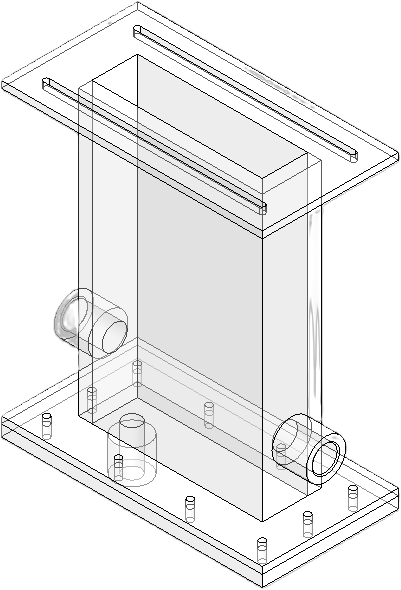
CAD view of the coalescence cell

Coalescence cell

A short rectangular cell with two capillaries entering through opposite walls and meeting at the centre, so that two bubbles can be brought together under controlled conditions. It measures the coalescence of bubbles, recorded by high-speed imaging against a backlight.
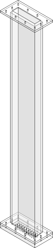
CAD elevation of the CFD-grade column

CFD-grade column

A rectangular column with a controlled injection sparger where each hole can be operated independently, giving measurements clean and repeatable enough to serve as a validation case for the project’s numerical work.
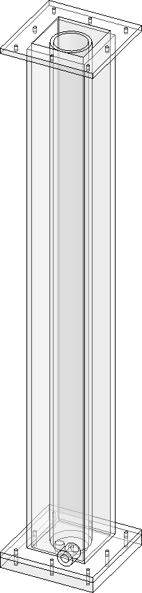
CAD elevation of the mass-transfer column

Mass-transfer column

A circular column enclosed by a square enclosure to remove refraction effects in image analysis, dedicated to the interfacial mass transfer between the gas and the liquid — the step that connects the bubble-scale work to the CO₂ absorption the project is aiming at.

Large scale · Work package D

Large-diameter bubble column

CAD elevation of the large-diameter bubble column

A circular large-diameter column (4.5 m height, 0.39 m inner diameter) dedicated to flow patterns, coherent structures and the local and global fluid-dynamic properties along the Ω-curve.

  • Column — 4.5 m height, 0.39 m inner diameter, 2.5 m initial liquid level, liquid recirculation, gas sparger region 0.40 m
  • Spargers — Interchangeable perforated plates with different hole diameters
  • Global measurements — Gas holdup, gas disengagement, global mass transfer
  • Local measurements — Three optical probes (void fraction, bubble size, velocity), wire-mesh sensors, image analysis near the sparger and at different radial/axial positions

Instrumentation

Instruments and computing resources

The measurement chain behind the two experimental scales, and the computing resources that process what it produces.

Measurement

Wire-mesh sensor

Gas fraction resolved over the whole cross-section of the column, at high acquisition rate, from the conductance between two crossing planes of wires.

Measurement

Optical probes

Local measurements at a point in the flow. Dual-tip probes give void fraction, bubble chord length and bubble velocity from the time each tip spends in the gas; Doppler probes give the velocity of the dispersed phase without touching it, from the frequency shift of the backscattered light.

Measurement

High-speed cameras

Phantom and FLIR cameras record the flow at high frame rate — the images behind Particle Shadow Velocimetry, bubble tracking, and the size, shape and velocity statistics drawn from them.

Measurement

Conductivity meter

For the measurements of the electrical conductivity of the liquid phase, which is related to the CO₂ uptake and impurity content.

Measurement

pH meter

pH of the liquid phase, monitored alongside conductivity while the solvent mixtures are prepared and while they take up CO₂.

Computing

NVIDIA H200 GPU

The compute behind the numerical side of the project: simulations and the image-analysis pipelines that turn recordings into bubble statistics.